After more than 80 years of use as a sensor element for deformation measurement, strain gauges have become a universal method. However, as the industry has increasingly higher requirements for measurement values and digital processing, traditional adhesive sensor strain gauges are facing new challenges. In order to meet these needs and open up new application areas, additive manufacturing technology can be used to achieve more flexible design, automation and reproducibility in the installation of strain gauges.
Traditional strain gauge and its application
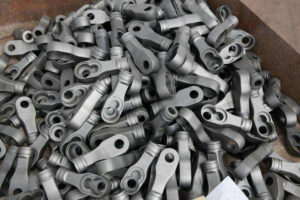
Strain gauges can be used to record component loads, such as force or moment, and changes in the shape (strain/compression) on the surface of these components (see Figure 1). For this reason, strain gauges have been continuously revised in recent decades to reduce measurement uncertainty. However, the basic working principle of the strain gauge has not changed. When force is applied, the electrical conductor deforms. The length and cross-sectional area of the conductor will change, which directly changes its measurable ohmic resistance.
Figure 1. Traditional bonded strain gauges and connecting wires on stainless steel parts.
The user first associates the strain gauge with the detailed procedures required to install it. This is because bonding requires not only many working steps and corresponding expertise, but also experience in the installation process and necessary manual sensitivity to convert the strain gauge provided on the carrier foil into a measuring point on the component for accuracy To measure. In principle, the working environment must be kept clean in order to apply a thin, non-polluting adhesive layer. For compact force sensors, such as household scales, hot melt bonding is used. Here, the adhesive-coated strain gauge is pressed onto the measuring point, and then the component is cured in an oven.
If the component cannot be placed in the oven due to its size, weight or temperature sensitivity, the so-called cold bonding method is used. After sanding the bonded area and degreasing, mark the expected strain gauge position. The marking and positioning of the strain gauges and the subsequent sticking and uniform distribution of adhesives are usually performed manually, so there will be a lot of uncertainty in the lateral positioning of the strain gauges. When the adhesive cures, press the strain gauge on it for about one minute. The thickness of the cured adhesive film may vary greatly, which will seriously affect the sensor’s responsiveness.

Therefore, there are two problems with the glue on the strain gauge. On the one hand, due to user error, manual steps lead to inconsistent quality. High-quality requirements can be met with some auxiliary tools; however, the workload and installation time will increase. If the quality of the measuring point is insufficient, the strain gauge must be destructively removed and a new one must be attached. On the other hand, the use of qualified personnel is the largest cost part of installing strain gages. For larger quantities, there is no or insignificant cost scaling effect. Therefore, the sensor needs to use an automated process.
In addition, the work of the subsequent measurement and data transmission chain has also become complicated, especially on rotating parts. The usual method is to use an inductive telemetry system to transmit measurement data and energy through inductive coupling. However, these systems are only suitable for mass production to a limited extent because they are prohibitively expensive and are not particularly robust. Other alternative methods, such as surface acoustic wave (SAW) or magnetostrictive sensor technology, are only suitable for certain materials or have proven to be susceptible to interference in field use. Therefore, they have not been able to establish themselves. The development of low-power industrial solutions for wireless data transmission is opening up new possibilities. Here, these possibilities will be used to put sensor technologies that do not require external energy into practice.
Additive material printing for strain gauge sensors
What opportunities can additive manufacturing provide here? After all, many 3D components can already be printed with different materials. The Fraunhofer Institute for Laser Technology (Fraunhofer ILT) and i4M Technologies (both in Aachen, Germany) have solved this problem and developed a prototype as described below.
In traditional strain gauges, the resistance measurement grid is usually superimposed between the carrier and the cover film. This foil strain gauge is bonded to the component with an adhesive. The strain of the component is transferred to the measurement grid through the two intermediate layers (see Figure 2a). In principle, the measuring net should be as close as possible to the surface of the component to avoid loss of force transmission. The change in bonding thickness will be reflected in the force transmission, and the response at the measuring point of the strain gauge may change. When the strain gauge is directly printed using a printing process (such as inkjet printing), a simpler layer system can be used between the part and the measurement grid (see Figure 2b). Only one intermediate layer is needed, which combines the function of force transmission and electrical insulation between the component and the measurement network.
How to create a strain gauge using 3D printing technology
In the additive manufacturing method shown here, three functional layers (insulation layer, metal measuring grid, and cover layer or encapsulation layer) are printed in sequence, and then each functional layer is functionalized. The functions of carrier film and adhesive in conventional strain gauges are taken over by a single insulating layer. In this way, the measurement grid can in principle be positioned closer to the surface of the component, which is expected to improve the transmission of strain to the sensory measurement grid.
Which processes are suitable for lamination? These processes should be digital, resource-saving, and work online. They have been proven to be powerful enough on an industrial manufacturing scale. The most important thing is to reduce the manufacturing cost of each sensor.
Before applying the additive-manufactured strain gauge to the component, laser radiation can be used to clean the surface of the component with interfering substances, such as rust, residual lubricant or oxide layer from previous process steps. This step can also be applied to roughened surfaces. Small areas under the microscope are selectively ablated, remelted or modified with pulsed laser radiation to increase the adhesion of the later applied layers.
Dispensers and inkjet printers can selectively deposit materials on the measurement points. Post-processing is performed with a high-efficiency light source (laser or LED), which can quickly couple the necessary energy into the printed layer without unnecessary heating of the part.
Hybrid polymers, such as ORMOCER invented by the Fraunhofer Institute for Silicate (Fraunhofer ISC; Würzburg, Germany), can be used as an electrical insulating material. It can be provided as an uncrosslinked viscous material and can be photoinitiated (ie, crosslinked by light irradiation). The material can be selectively applied by dispensing, so the hybrid polymer is only applied to the required area (see Figure 3). The CNC system guides the dispenser to ensure precise positioning. Then, a light source cures the layer in a few seconds. The following is a comparison of the construction steps of the standard foil base and the additively manufactured strain gauge layer.
The layer structure of the standard foil-based strain gauge:
Cover foil
Measuring grid
Carrier foil
Adhesive
Element
The layer structure of the strain gauge for additive manufacturing:
Package form
Measuring grid
Insulation (no glue)
Element
After the electrical insulation is formed on the metal part, the resistance sensor measurement grid will be printed. This is accomplished by inkjet printing nanoparticle metallic inks. The thin liquid ink contains metal nanoparticles, adjuvants and solvents, and can be printed on the insulating layer with high resolution like images printed on a color printer. There is no need for a template or mask as in the etching process, and the measurement grid can be digitized to suit specific measurement tasks. In order to make the metal ink conductive, it is necessary to evaporate volatile components such as solvents and auxiliary materials, and sinter the metal particles together. Laser sintering is particularly suitable for this thermal post-processing step because it is not necessary to heat the entire assembly in an oven. This is an important advantage, especially for temperature-sensitive substrates such as hardened steel. The final packaging of the measurement grid can protect it from environmental influences and can be manufactured using the same materials and processes as the insulating layer.
Digital printed strain gauges that are post-processed by laser can basically achieve constant quality, regardless of manual processes, and have attractive costs in mass production. This method has particular advantages in highly flexible small-batch production, because it is possible to create a customized design without reinstalling the mold. However, all the challenges of process development have not yet been resolved. For example, so far, only limited metal inks and insulating materials can achieve material matching temperature compensation or definite force transmission, or have been developed for laser functionalization processes. Therefore, Fraunhofer ILT is working with research partners and industrial users for further development.
From measuring point to smart sensor
However, it is not enough to use strain gauges as sensors, because the measurement data of smart components must be digitized, transmitted, and analyzed. Measurement data is now “smart data” (economically available data), which means remaining service life, automatic maintenance schedules, optimized control strategies, etc., all of which form the basis of concepts such as predictive maintenance . In order to accurately measure the component load, a strain gauge-based measuring point must be applied in the force flow. However, there is not much space, especially in modern machines. In addition, the price pressure of this solution is very high, especially when the quantity increases and the solution needs to be prepared for mass production.
A highly integrated low-power radio telemetry technology was developed to transmit data from sensors in additive manufacturing and applied to components along with strain gauges (see Figure 4). Use the latest commercially available hardware and use optimized firmware to maximize power efficiency:
Ultra-low-power system-on-chip consisting of Cortex M4 MCU and 2.4 GHz radio modem
Analog measurement front end with 24-bit ADC, integrated signal amplifier and reference voltage source
Six additional DOF MEMS sensors (accelerometer, gyroscope) and temperature sensor
Lithium-ion battery or lithium primary battery with suitable charging electronics and protection circuit
A specially developed protocol is used for data transmission in the 2.4 GHz frequency band. Compared with Bluetooth and other industrial protocols, this protocol can achieve higher data rates and lower latency. The maximum possible sampling rate is 19.2 kHz, and it can also be streamed live. However, the power requirements and battery runtime directly depend on the selected sampling rate. Since the strain gauge measurement bridge has the highest power requirements, it operates in pulse mode, but this is only possible at certain sampling rates. In addition, all components can run in a short time with a higher sampling rate in a low-power sleep mode. Depending on the battery, it can run continuously for hours or even days at a frequency of 19.2 kHz.
Thanks to this solution, high-performance, energy-autonomous sensors can produce highly usable components within the constraints of a small installation space. This sensor technology has been successfully applied to various technical systems, from gears and roller bearings rotating in warm oil to railway systems or wind turbines under strong electrical interference fields and severe vibrations. The computing power on the MCU also allows edge analysis (such as FFT) on the sensor. These smart sensors can achieve a substantial reduction in the amount of transmitted data, thereby further improving energy efficiency through edge computing. In addition, online algorithms in the sensors make it possible to improve the quality of the measured values obtained-for example, through sensor fusion or suitable filters.
However, one limitation of the telemetry solution shown here still exists: battery operation. Many years of battery life are feasible, but they are limited-which is why energy harvesting methods are now starting to work. At i4M Technologies, promising methods based on temperature and radio frequency acquisition have been successfully studied.
Link to this article:
Reprint Statement: If there are no special instructions, all articles on this site are original. Please indicate the source for reprinting:https://www.cncmachiningptj.com/,thanks!
 3, 4 and 5-axis precision CNC machining services for aluminum machining, beryllium, carbon steel, magnesium, titanium machining, Inconel, platinum, superalloy, acetal, polycarbonate, fiberglass, graphite and wood. Capable of machining parts up to 98 in. turning dia. and +/-0.001 in. straightness tolerance. Processes include milling, turning, drilling, boring, threading, tapping, forming, knurling, counterboring, countersinking, reaming and laser cutting. Secondary services such as assembly, centerless grinding, heat treating, plating and welding. Prototype and low to high volume production offered with maximum 50,000 units. Suitable for fluid power, pneumatics, hydraulics and valve applications. Serves the aerospace, aircraft, military, medical and defense industries.PTJ will strategize with you to provide the most cost-effective services to help you reach your target,Welcome to Contact us ( [email protected] ) directly for your new project.
Link to this article:3D printing technology improves the manufacture and use of strain gauge sensors and eliminates the interference of human factors
Reprint Statement: If there are no special instructions, all articles on this site are original. Please indicate the source for reprinting.:Silicone And Casting,Thanks!^^